30+ uart transmitter block diagram
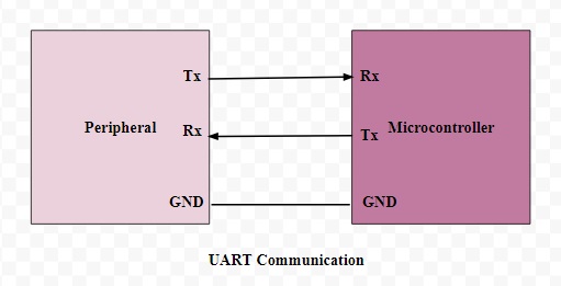
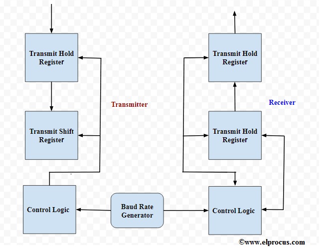
UART A simplified block diagram of the UART is illustrated in Figure 1-1. The communication process between the computer.
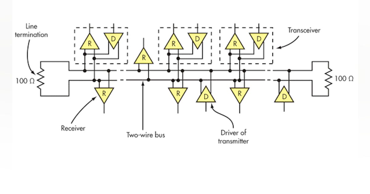
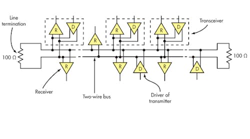
What S The Difference Between The Rs 232 And Rs 485 Serial Interfaces Electronic Design
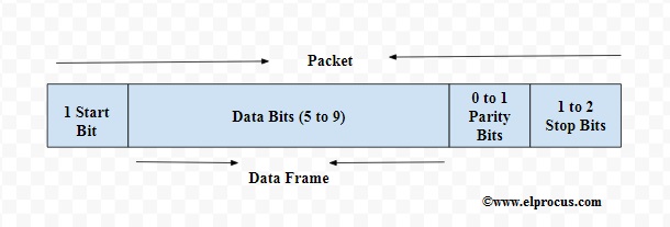
UART Character Transmission Below is a timing diagram for the transmission of a single byte Uses a single wire for transmission Each block represents a bit that can be a mark logic 1.

. The Universal Asynchronous Receiver Transmitter UART module is a serial IO communications peripheral. The UART module consists of the following key hardware elements. Guide describes the universal asynchronous receivertransmitter UART.
Free with a 30 day trial from Scribd. It contains all the clock generators shift registers and data buffers necessary to. Given the UART Transmitter Receiver Diagram from an ARM M4 MCU.
30 13 Line Control Register LCR Field Descriptions. If we remember the old computer parts like printer mouse the keyboard is associated with the help of connectors. 13 Functional Block Diagram.
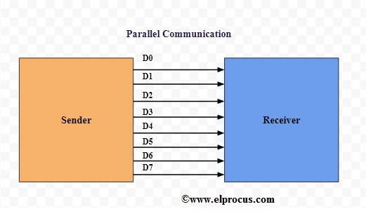
The evolution of UART ICs is given below. The heart of the transmitter is the transmit shift register UxTSR where parallel data 9-bit word are converted to serial data. We used Virtex 5 board for testing of UART as it holds.
Baud Rate Generator. UART Transmitter Block Diagram Transmit Buffer Register Transmit Buffer Register from SCIENCE 102 at University of Santo Tomas. The first PC UART 8250 was manufactured by National Semiconductors.
The UART transmitter block diagram is shown in Fig. Go Board UART Universal Asynchronous ReceiverTransmitter Learn to Communicate with the Computer Part 2 Transmitter In the previous project you learned how to receive data from. The heart of the transmitter is the transmit shift register UxTSR where parallel data 9-bit word are converted to serial data.
The UART transmitter block diagram is shown in Fig. UOTX OE BE PE FE Stop 7 6 5 4 3 2 1 0 Start Stop 7 6 5 4 3 2 1 0 Start Shift Data 0. Further it is tested on hardware boards ie.
The system schema full broken link removed Serial_Transmitter VHDL code I. UART comprises three main modules baud rate generator transmitter receiver. The eight channels of UART are called as octal of UART.
Hello world D I need help to make a transmetter UART in schematic block with Quartus II. One Robot a Dozen Engineers and the Race to Revolutionize the Way We Build Jonathan Waldman. Question 4 30 Points.
Basics Of Uart Explained Communication Protocol And Its Applications
Uart Communication With Nuvoton N76e003 Microcontroller Serial Communication Microcontrollers Communication Circuit Diagram

Uart Diagram Back To Basics Education Simple Art
Basics Of Uart Explained Communication Protocol And Its Applications
Why Do We Implement Rts And Cts In Uart Although This Is Typically What The Start And End Bits Functionally Did Quora

8251 Is A Usart For Serialdatacommunication As A Peripheral Device Of A Microcomputer System The 8251 Receives Paralle Block Diagram Reading Writing Modem
Basics Of Uart Explained Communication Protocol And Its Applications
Basics Of Uart Explained Communication Protocol And Its Applications
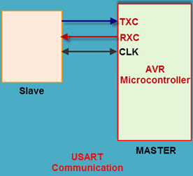
Ateml Avr Microcontroller Serial Data Communication Usart
Xu3cphnr5shuom
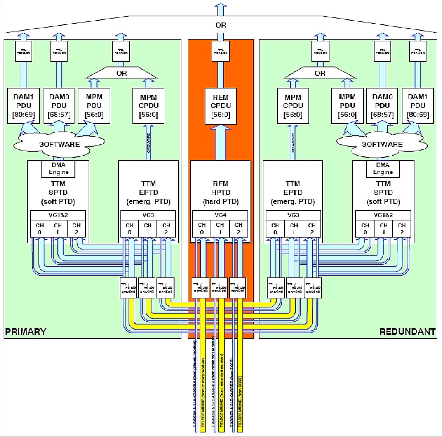
Proba 2
What Is Uart And Why Is It Important Quora
Why Do We Implement Rts And Cts In Uart Although This Is Typically What The Start And End Bits Functionally Did Quora
What Is Uart And Why Is It Important Quora

Popular Circuits Page 233 Next Gr
Basics Of Uart Explained Communication Protocol And Its Applications
What S Difference Between Analog And Digital Communication In Terms Of Block Diagram Attached Below E G After Source Channel Encoding Before Modulation Data Is Binary Am Fm And Pm Have Analog Signal